11
2026
What Are the Components of a Coefficient of friction (COF) testing Machine?
 An article by admin

Understanding the components of a friction testing machine helps you make informed decisions about your quality control and material selection processes. We know that reliable data is critical for your product development and packaging performance. By breaking down the core systems, we aim to clarify how these instruments deliver the precise measurements you require. This knowledge ensures you can effectively evaluate material performance for your specific applications.

Friction Force Measurement System
The friction force measurement system is the core component responsible for quantifying the resistance encountered when two surfaces slide against each other. It typically consists of a highly sensitive load cell or force transducer that detects the minute forces generated during the test. This sensor is connected to a signal conditioner and a data acquisition system that amplifies and converts the analog force signal into a digital readout. The system is calibrated to provide accurate and repeatable measurements of both static friction, the force required to initiate movement, and kinetic friction, the force needed to maintain it. This data is essential for quality control and material characterization in various industries. Users can also choose professional coefficient of friction testing services for detailed analysis.
Sample Mounting Platform
The sample mounting platform provides a stable and level base for securing the test specimens. It is designed to hold the stationary sample, or the base substrate, firmly in place without any slippage that could compromise the test results. The platform’s surface is often machined to a high degree of flatness and may include clamps, vacuum plates, or double-sided adhesive tapes to accommodate different material types, from flexible films to rigid sheets. A parallel alignment mechanism is crucial to ensure the sled and the platform make uniform contact. This component’s rigidity and precision are vital for maintaining consistent test conditions, a principle emphasized by instrumentation providers like Labthink. Proper mounting is fundamental to achieving reproducible data that accurately reflects the material’s frictional properties.
Controlled Motion Actuator
The controlled motion actuator is the component that generates the relative movement between the two test surfaces. It is responsible for pulling the friction sled across the mounted sample at a constant, pre-set speed. This actuator can be a stepper motor, a servo motor, or a lead screw mechanism, chosen for its ability to deliver smooth, non-accelerating motion. The consistency of the travel speed is critical, as variations can directly affect the measured kinetic friction values. The system includes controls to program the test speed, travel distance, and return cycle. By ensuring a uniform and repeatable sliding motion, this component allows for direct comparison of results between different materials or production batches, forming the basis for reliable performance analysis.
Conclusion
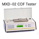
In our work, we utilize instruments like the MXD-02 Coefficient of Friction Tester, which integrates these core components into a single system. This instrument measures static and kinetic coefficients of friction and is used on materials including plastic films, rubber, paper, fabrics, and metals. Our tester conforms to standards such as ISO 8295, ASTM D1894, and GB 10006. It is a product of the company Labthink, and we rely on this friction testing machine for consistent and standardized material evaluation.


Leave a comment
Videos for Friction Tester
Recent Posts
- Labthink MXD-02 Coefficient of Friction Tester: Precision Testing for a Wide Range of Materials
- Understanding the Role of Friction Analysis in Material Testing
- Coefficient of Friction Testing Services for Businesses: Ensure Quality and Precision
- How you can easily perform a COF test for package materials?
- What Are the Components of a Coefficient of friction (COF) testing Machine?